Still seems to me that the Raspberry Pi is the way to go to introduce CS into elementary classrooms. The cost, community support, and ease of use is fantastic.
The newest update to Raspbian includes offline support for Scratch and GPIO pin control.
Today I built my new prototype on the breadboard and tested it. I had a few problems along the way but was able to debug them fairly easily. I would sometimes put the wrong leg of an LED in or have a resistor touch a leg of an LED and I missed a bit of the code expanding it to 10 pins.
The sequence is for the first LED to light up, a delay of 1/4 second (250), then the next until all ten are lit, and then the first goes off with the rest following. Changing the various delays is easy of course, but I haven’t experimented with that yet.
The prototype is up at the 123D site. There you can see a simulation and the code. One thing about the site that is difficult is the gestured zoom feature – it’s finicky, so if you find yourself stuck with no where to go press refresh on your browser. Using 123D is easy and intuitive. I could easily see using it to curate students’ circuits without the fuss and expense of the Arduino. Without empirical evidence, my guess is that you could function nicely in a class with 4-5 actual Arduinos in a class of 16-20 students using 123D.
After testing my sensor, and getting a clearer picture of how the four LEDs circuit works, I returned to the breadboard and rewired my circuit.
if (digitalRead(6) == HIGH && digitalRead(7) == LOW) {
// Green LED on:
digitalWrite(green, HIGH);
digitalWrite(amber, LOW);
}
else {
digitalWrite(green, LOW);
}
if (digitalRead(7) == HIGH && digitalRead(6)==LOW) {
// turn LED on:
digitalWrite(blue, HIGH);
digitalWrite(amber, LOW);
}
else {
digitalWrite(blue,LOW);
}
if (digitalRead(6) && digitalRead(7) == HIGH){
digitalWrite ( red, HIGH);
digitalWrite(amber && blue && green, LOW);
analogWrite(amber, LOW);
}
else {
digitalWrite(red,LOW);
}
if (digitalRead(6) && digitalRead(7) == LOW){
digitalWrite(red && blue && green && amber, LOW);
Serial.print(“Photo 1: “);
Serial.print(digitalRead(6), DEC); // Display Out 1 value
Serial.print(“; “);
Serial.print(“Photo 2: “);
Serial.println(digitalRead(7), DEC); // Display Out 2 value
delay(100);
}
My goal was to also save this to my collection at Autodesk 123D Circuits, but unfortunately the components list didn’t include a six pin 4-Direction tilt sensor.
As you can see in one of my previous posts, I need to have much further understanding of how the tilt sensor works so I can debug when things go beyond my knowledge.
For me to learn something and to be able to teach it I have to go far ahead of myself and then back off – go a little further – and back off again.
Now I have to think about what it would be like to teach this to an unknown group of students. How would I present the Arduino? What tools and components would I need? What would my budget look like? How do I set up a consistent teaching scenario?
Having discovered Autodesk’s 123D has helped me to concretize some of my thinking on this. What I did today was to go back (yet again!) to an early circuit and replicate it using the excellent bookIntroduction to Arduino, A piece of cake! by Alan G. Smith. I attached my breadboard to a piece of cardboard and attached the Arduino to this as well. This will help keep things oriented well and prevent the Arduino from flipping around when it’s plugged in. It would be my classroom’s culture to keep this orientation when using the bb setup with 123D.
The next step was to create the circuit on the breadboard and 123D:
And then to run them both:
I feel good about this setup because now I can teach circuits using alligator clips and Serial Bus, on a breadboard, and using 123D. Using 123D will help to flip my classroom so that experiments can be made away and brought into the lab for replication. I also find that this reiteration helps to retain the concepts learned.
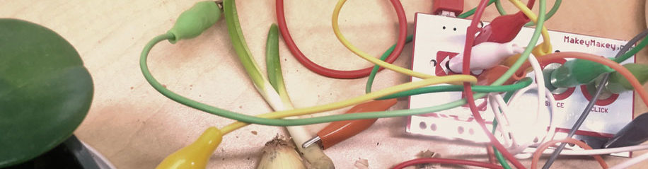
My #42 Tech Ed endorsement is helping me to learning how to use a breadboard with Arduino to make circuits. At first I learned how to make them very simply with Makey Makey and connecting 3 LEDs with a Serial Bus, but I really liked the breadboard because my mind could follow the circuit’s path more intuitively. So I advanced my work into breadboards with Pulse Width Modulation, coding a switch, and sensor.
As I head into choosing what I want to do for my final project, I’ve used this week to explore using Autodesk’s 123D 3D modeling application to recreate and create new circuits. My hope is to integrate this excellent tool with whatever I decide my Final Project to be.
In doing the next part of my assignment, Coding a Sensor, I needed to be sure I was using the correctly rated resistor of 10KΩ. I had two kinds, so I had to figure out which was which. After learning a little on Wikipedia: Electronic Color Code Resistor Color Coding
I found a Resistor Calculator on HobbyHour.Com that was helpful. The one I had been using is what I need, 10KΩ. I’m having trouble distinguishing the others I have because I can’t really tell the difference between black and blue in the second column to well. If it’s black it’s 500KΩ, but the calculator warns me that is a Non-standard 5% (E24) value! If I use blue it doesn’t warn and says that it’s 560KΩ. That number seems high, but I don’t know enough to know if it’s high or not. Anyway, I have the resistor I need.
Simple Light Reading With LDR + Arduino – bildr.blog
“The LDR changes its resistance with light so we can measure that change using one of the Arduino’s analog pins. But to do that we need a fixed resistor (not changing) that we can use for that comparison (We are using a 10K resistor). This is called a voltage divider and divides the 5v between the LDR and the resistor. Then we measure how much voltage is on the LDR using the analog read on your arduino, and we have our reading. The amount of that 5V that each part gets is proportional to its resistance.”
Okay. Got that.
“With the arduino analogRead, at 5V (its max) it would read 1023, and at 0v it read 0. So if the the LDR and the resistor have the same resistance, the 5V is split evenly (2.5V), to each part. (analogRead of 512)
But if the LDR is hit with a ton of light and is reading only 1K of resistance, the 10K resistor is going to soak up 10 times as much of that 5V. So the LDR would only get .45V (analogRead of 92).
And if it is in a dark room, the LDR may be 40K or resistance, so the LDR will soak up 4 times as much of that 5V as the 10K resistor. So the LDR would get 4V (analogRead of 818).”
OK – seems accessible so far…
I was given a tutorial to use to code the Arduino for the photocell, but I’ve grown so accustom to my breadboard that I get lost if the description entails alligator clips and wires. I like the breadboard as it lays things out well for me to contemplate what’s happening more carefully. So I found this tutorial from Adafruit: Using a Photocell.
Breadboard using 2 resistors, one LDR, and one LED. Ravine crossed for the LED.
int photocellPin = 0; // the cell and 10K pulldown are connected to a0
int photocellReading; // the analog reading from the sensor divider
int LEDpin = 11; // connect Red LED to pin 11 (PWM pin)
int LEDbrightness; //
void setup(void) {
// We’ll send debugging information via the Serial monitor
Serial.begin(9600);
}
Serial.print(“Analog reading = “);
Serial.println(photocellReading); // the raw analog reading
// LED gets brighter the darker it is at the sensor
// that means we have to -invert- the reading from 0-1023 back to 1023-0
photocellReading = 1023 – photocellReading;
//now we have to map 0-1023 to 0-255 since thats the range analogWrite uses
LEDbrightness = map(photocellReading, 0, 1023, 0, 255);
analogWrite(LEDpin, LEDbrightness);
delay(100);
}
• Which coding concepts were introduced by coding the sensor (photocell)?
a) ≠coding, but learning about resistors/ohms was helpful.
b) Using variables again in a new form:
Serial.print(“Analog reading = “);
Serial.println(photocellReading);
LEDbrightness = map(photocellReading, 0, 1023, 0, 255);
analogWrite(LEDpin, LEDbrightness);
• Describe the computational thinking that you are practicing when creating/coding with the sensor (photocell):
Now that we are bringing in analog readings into the mix I’m having to keep two different levels of thinking in mind at the same time. I’m struggling with that a little now.
To further extend my understanding (and my disequilibrium) around coding switches I have taken a project from the book I mentioned previously, Introduction to Arduino: A piece of cake!, by Alan G. Smith, September 30, 2011, that uses two buttons, one LED, a resistor, and code that uses Pulse Width Modulation (PWM). I’ve seen the PWM before in another exercise and this project has helped reinforce the notion.
Breadboard with one LED, two switches, one resistor. +/- are wired into right column.
const int kPinButton1 = 2;
const int kPinButton2 = 3;
const int kPinLed = 9;
• Which coding concepts were introduced by coding two switches?
Just adding another switch wouldn’t have been too interesting without using PWM to differentiate between the use of the two switches. What makes this project interesting is introducing ‘– and ++’ to make the LED brighter and dimmer.
ledBrightness = constrain(ledBrightness, 0, 255); “guarantees the value of ledBrightness will be between 0 and 255 (including 0 and 255)”
analogWrite(kPinLed, ledBrightness); “uses analogWrite to tell Arduino to perform PWM on that pin with the set value.”
delay(20); “delays for 20 milliseconds so that we won’t make adjustments faster than 50 times in a second. (You can adjust this to find where you think the best response is to your pressing the buttons.) The reason we do this is that people are much slower than the Arduino. If we didn’t do this, then this program would appear that pressing the first button turns the LED off and pressing the second button turns it on.”
• Describe the computational thinking that you are practicing when creating/coding two switches:
Change of state through a variable. Taking human factors in mind when programming – without the delay the LED would look like it’s just turning off.
• Which coding concepts were introduced by coding a switch?
• Describe the computational thinking that you are practicing when creating/coding a switch:
I used a new (to me) book that I’m finding very handy to set up two types of switches, Introduction to Arduino: A piece of cake!, by Alan G. Smith, September 30, 2011.
The first is a simple one button switch:
Breadboard with one LED, one switch, one resistor. +/- are wired into right column.
• Which coding concepts were introduced by coding a switch?
Two things here:
1) HIGH = ‘On’ | high voltage & LOW = ‘Pressed ‘ | low voltage.
2) if/else statements
• Describe the computational thinking that you are practicing when creating/coding a switch:
I will be the first to admit that my brain isn’t ‘wired’ for the computational thinking that coding requires, it neither comes naturally or easily and it takes many iterations in different forms for me to start to take on concepts and show understanding.
It isn’t easy for me to divorce the physical thing that I see, the button being up or “HIGH” to the electronic reality of the circuit. It is when the button is down that the circuit is complete and ground is connected to pin 2. When it is not pushed down the circuit is from the +5V through the resistor and the Arduino sees the +5V. (HIGH). Again, I will need to this type of thing a few more times before it really takes hold.
I’m working on understanding if/else statements.
From the book: “An if statement can have an else clause which handles what should be done if the if statement isn’t true.”
If the button is pressed then turn on the LED. If not (else) keep the LED off.
I’m working with a class of middle school children locally. They’re the type of kids who for many reasons aren’t typically motivated to create. They are highly motivated to consume media and will do so whenever they have the chance, but their teacher is trying to change that dynamic. I’ve offered him the use of a MaKey MaKey, and he’s going to try to raise the funds to buy a few more. I’ll follow up on this post, but I’m already really encouraged with the reception that it received today:
All I did for them was plug it in and get the MIT Scratch Drum Machine up for them and let them do the rest. A little later, after they got the idea of a a small circuit I gave them a Serial Bus I made for another project the night before and that let more kids in on the human drum kit. I’ve encouraged the teacher to let them discover and create on their own. I’ll go back next week and see where they go. I’m also helping them to work with Zoombinis – we’re going to look at ways to move the concepts off the game and into other creative projects and transferring the skills to other areas.